


 Telegram
 Вконтакте
 Дзен
 Youtube
 Rutube
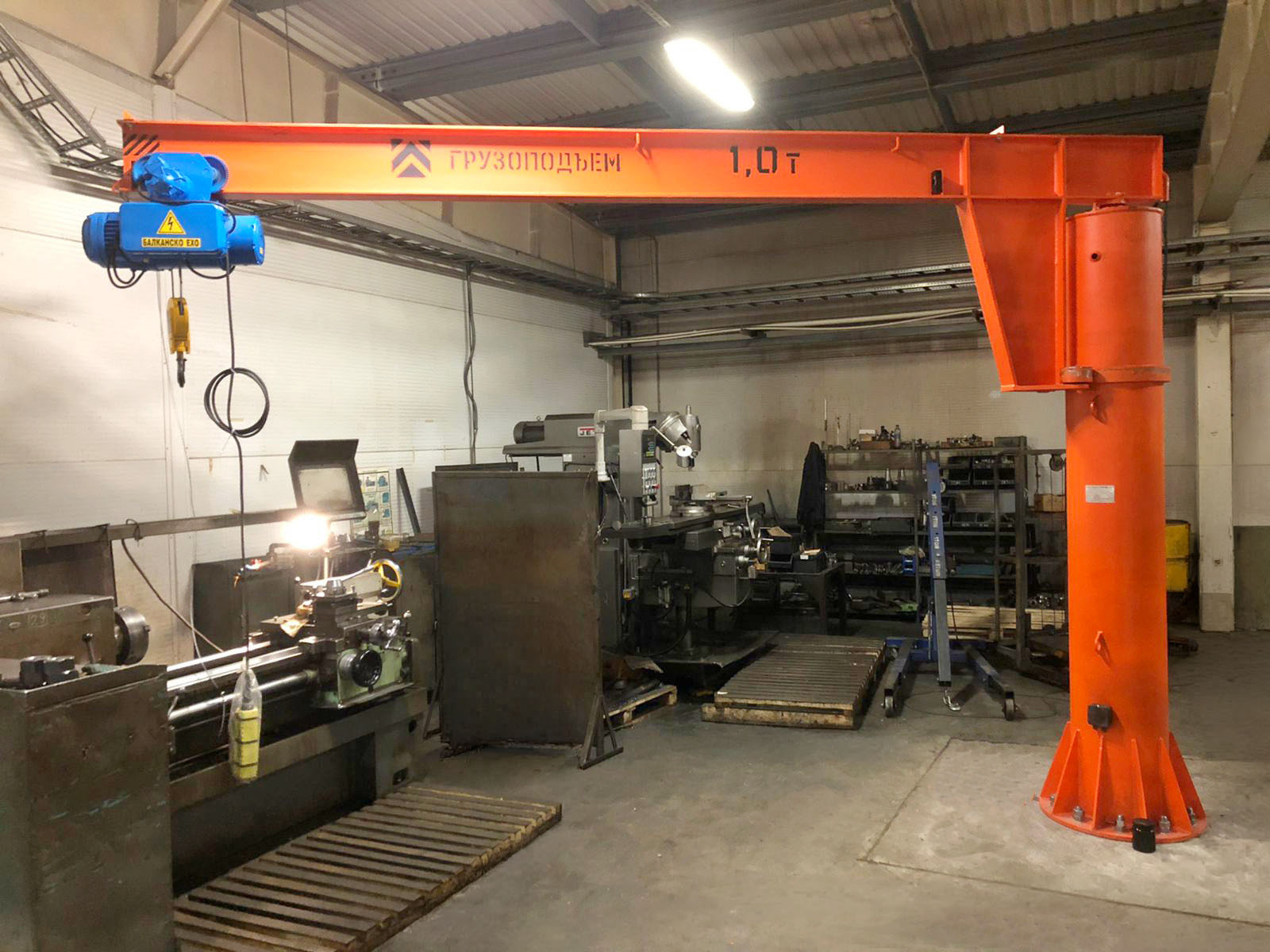
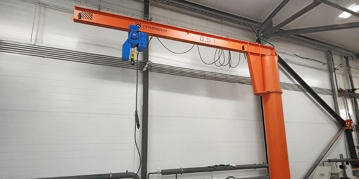
Pillar jib crane with a 360° angle of rotation and manual slewing KKR3 0.5 tons
Thanks to its robust design and simple operation, the jib crane with a lifting capacity of 0.5 tons will become a reliable assistant for a variety of tasks. The declared load capacity allows you to effectively move medium-sized and heavy loads, making it indispensable equipment on production lines and in warehouses. The reach of the crane boom can reach up to 10.0 meters (for wall-mounted devices) and up to 12.0 meters (for cranes on the column), which increases its working radius, and the boom itself can be rotated by 180 degrees (in the first case), 270 or 360 degrees (respectively) to ensure optimal coverage of the working area. Lifting heights of up to 36.0 meters are available, providing greater flexibility in task performance.
The 500,0 kg capacity cantilever cranes offer high maneuverability and precision. They can also be equipped with an electric drive for increased productivity and comfort of use. These cranes can be easily integrated into existing production processes and can be customized to best suit your requirements. For added efficiency and safety, Load Lifting Works offers a wide range of optional extras.
- crane boom (console) — 1 pc.
- crane column with lower support flange* — 1 pc.
- crane control box** (with the exception of cranes in the VZI version)
- gear motor 1-2 pcs.** (depending on the boom departure and lifting capacity of the crane)
- cable products**
- hoist (when delivered complete with a hoist)
- power supply to the crane (optional)
- power supply to the hoist (optional)
- other parts (the list of components depends on the configuration and set of options of the crane you ordered and may differ from the one given in this section of the site)
- crane documentation (passport, crane operation and installation manual, passports and instructions for individual crane components manufactured at other enterprises and supplied with this crane, packing list, waybill).
*For cranes on columns.
**For models with electric drive.
The above configuration is basic and may differ significantly from the actual one. If you need complete information on this issue, please contact the nearest sales department.
| Name of the option | Description of the option |
| Load capacity limiter | It is used as an additional safety device along with limit switches and a load drop protection device in case of phase breakage. It is installed, as a rule, in cases where work is carried out with different loads, the mass of which is not always known. If the weight of the load exceeds the lifting capacity of the hoist, the limiter blocks the lifting process. The option is available for cranes equipped with an electric hoist, since the limiter is mounted on the lifting mechanism of the hoist. |
| Sound and light alarms | The alarm is activated when the jib crane is turned on, warning employees to leave the danger zone. Depending on the conditions of the working area, it is recommended to install a light or sound alarm. The option is available only for electric jib cranes. |
| Radio control | Allows you to control the crane from a distance using the remote control. The option is available for electric jib cranes or for cranes equipped with an electric hoist. The package includes a 6-button remote control with an emergency stop button, a radio signal receiver (installed on the hoist or on the crane control box or next to the control box). |
| Electric motor with boom turn brake | The built-in brake allows you to stop the crane boom in the right place of non-stop movement of the equipment by inertia. It is impossible to manually fix the console at a strictly necessary point. Visually, the brake on the crane structure is not visible, since it is an element of the gearbox motor design. The option is recommended to be installed for cranes with the placement category U1 and U2 to prevent spontaneous movement of the boom in the parking position with wind gusts and other external factors. |
| Carport for parking hoists when performing "On the street" | They are used on cranes of the placement category U1 (on the street) to protect the electric hoist from direct precipitation. It is recommended for installation by manufacturers of cranes and hoists, since the hoists themselves usually do not provide alternative protection from precipitation. |
| A canopy for a hoist for the entire length of the span when performed "On the street" | They are used on cranes of the placement category U1 (on the street) to protect the electric hoist from direct precipitation. It is recommended for installation by manufacturers of cranes and hoists, since the hoists themselves usually do not provide alternative protection from precipitation. |
| Power off on the crane column | Allows you to turn on/off the tap power. It is located at a height of about 1500 mm from the lower flange of the crane. It is a two-button post in a protective (metal) casing. |
| Electric limit switches for the movement of hoists along the crane boom | They are used to limit the path of the electric hoist along the crane console. |
| Anchor system for fixing the crane to the foundation | This option refers to the stage of installation of the structure. Anchors are needed to attach the crane to the foundation. As a rule, we offer an anchor system for implementation on a prepared foundation. On an unprepared foundation, so-called mounting studs are used. |
| Load drop protection device in case of phase breakage | An additional safety device along with a load capacity limiter and limit switches. |
| Logger of crane operation parameters | Registers the operating conditions of the crane, including modes, duration and volume of loading. It is installed only when the crane is equipped with an electric rope hoist. |
| Crane operating time indicator | Controls the operating time of the crane, allowing time to carry out the necessary maintenance, maintenance and overhaul. It is built either into the door of the crane control box, or inside it. |
| Frequency control of the boom rotation speed | The frequency converter is installed in the crane control box for the possibility of adjusting the boom rotation speed in a certain range. It can also perform smooth start and braking. |
| Engine cooling system | It is recommended to use when installing a frequency converter, which will significantly limit the standard speed of movement of the crane, to prevent overheating of electric motors. |
| Input throttle | Smoothes the front and reduces the amplitude of the emission of bursts of alternating power supply voltage. Reduces the amplitude of the ripple current consumed by the frequency converter from the mains. |
| Platform and ladder for maintenance of hoists and crane components | When ordering a jib crane with a height of more than 3 meters, it is recommended to immediately provide ways of servicing the hoist, oil change and other maintenance operations. One of the options is to install a horizontal platform on the column at a human-height distance from the console and a ladder welded to the crane column leading to this platform. |
| Heated crane control box | Allows you to operate a jib crane at air temperatures up to -20 g. C (inclusive). It is required to be installed on all cranes that are operated at an air temperature below -10 g. s. Requires additional installation of a frequency converter. |
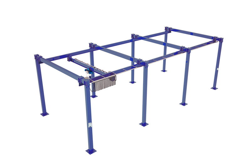
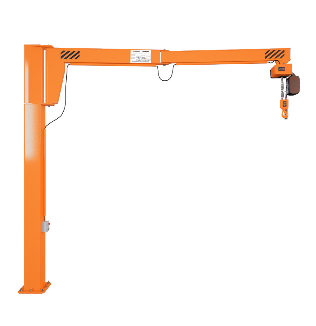
Other types of equipment
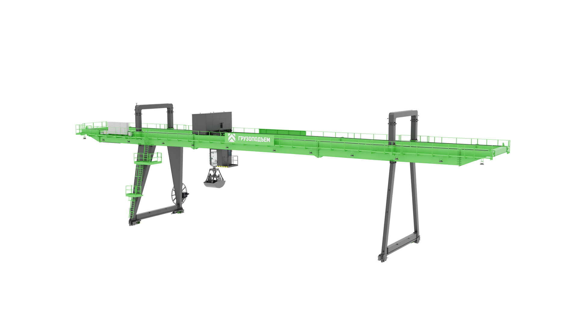
The company manufactures couplings with the following configurations:
With brake pulley
Without brake pulley
Without mating half-coupling
With mating half-coupling
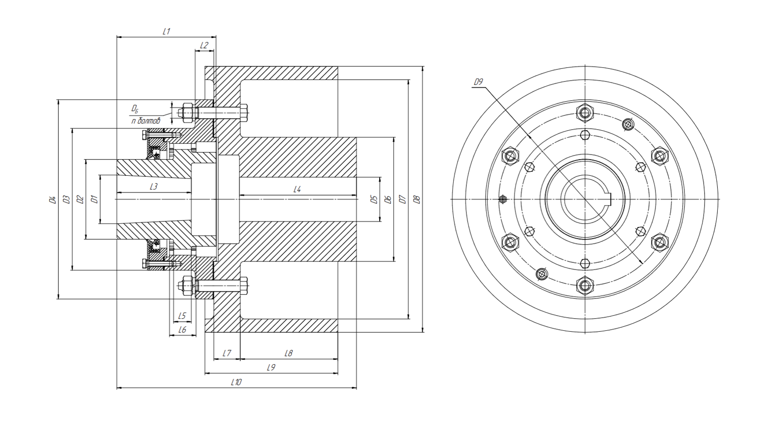
Fig. 2. Drawing of the MZ coupling with brake pulley version.
Table 1. Specifications of MZ couplings with brake pulley
Тип | m | z | Мкр, кгс∙м | D1* | D2 | D3 | D4 | D5* | D6 | D7 | D8 | D9 | L1* | L2 |
МЗ-1 | 2,5 | 30 | 71 | 36 | 55 | 110 | 160 | 35 | 100 | 170 | 200 | 140 | 86 | 18 |
МЗ-2 | 2,5 | 38 | 140 | 40 | 70 | 125 | 185 | 50 | 125 | 270 | 300 | 160 | 112 | 21 |
МЗ-3 | 3 | 40 | 315 | 55 | 90 | 160 | 225 | 65 | 140 | 270 | 300 | 195 | 112 | 21 |
МЗ-4 | 3 | 48 | 560 | 75 | 110 | 185 | 265 | 90 | 180 | 360 | 400 | 230 | 143 | 21 |
|
|
| ||||||||||||
| L3* | L4* | L5 | L6 | L7 | L8* | L9 | L10* | DБ | n | DБ | Масса, кг |
|
|
МЗ-1 | 60 | 60 | 15 | 26 | 20 | 60 | 100 | 216 | 12 | 4 | 12 | 19 |
|
|
МЗ-2 | 84 | 84 | 23 | 29 | 30 | 74 | 150 | 224 | 12 | 4 | 12 | 43 |
|
|
МЗ-3 | 84 | 112 | 30 | 28 | 30 | 99 | 150 | 270 | 16 | 6 | 16 | 52 |
|
|
МЗ-4 | 107 | 107 | 38 | 36 | 40 | 142 | 190 | 322 | 16 | 6 | 16 | 108 |
|
|
By agreement with the customer, it is possible to manufacture MZ-1 with a Ø160 mm brake pulley and MZ-4 with a Ø500 mm brake pulley.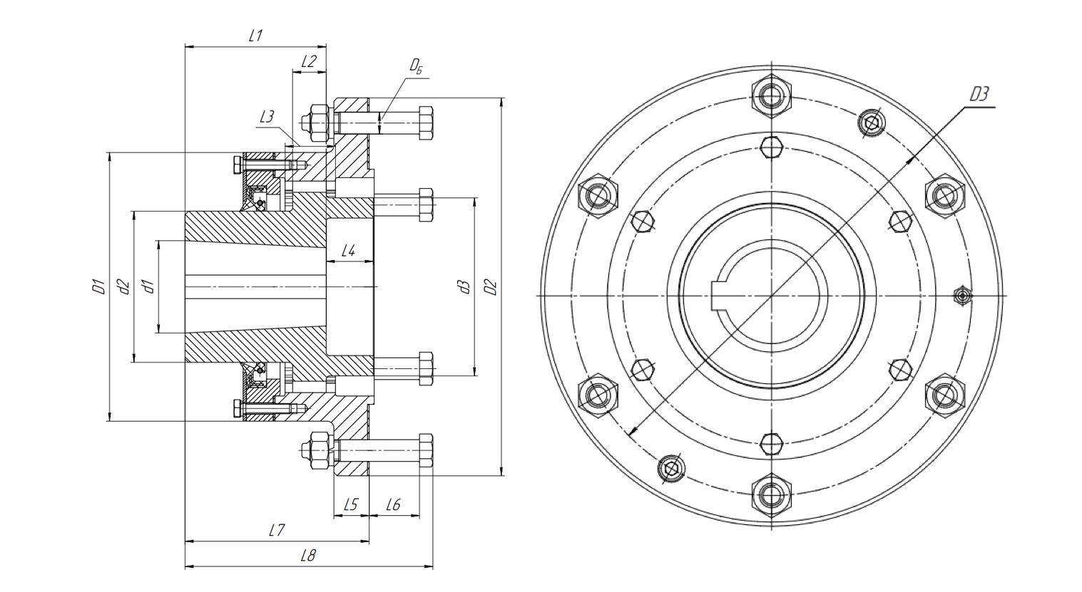
Fig. 3. Drawing of the MZ coupling in version without brake pulley.
Table 2. Specifications of MZ couplings without brake pulley
Тип
m
z
Мк,
кгс∙м
N,
об/мин
d1
d2
D1
D2
D3
L1
L2
L3
L4
L5
L6
L7
L8
DБ
nБ
Масса,
кг
МЗ-1
2,5
30
71
6300
36
55
110
160
140
60
12
15
26
18
20
86
112,5
12
4
5
МЗ-2
2,5
38
140
5000
40
70
125
185
160
84
15
23
29
21
30
112
147,5
12
4
8
МЗ-3
3
40
315
4000
55
90
160
225
195
84
20
30
28
21
30
112
147,5
16
6
13
МЗ-4
3
48
560
3350
75
110
185
265
230
107
25
38
36
21
30
143
180,5
16
6
20
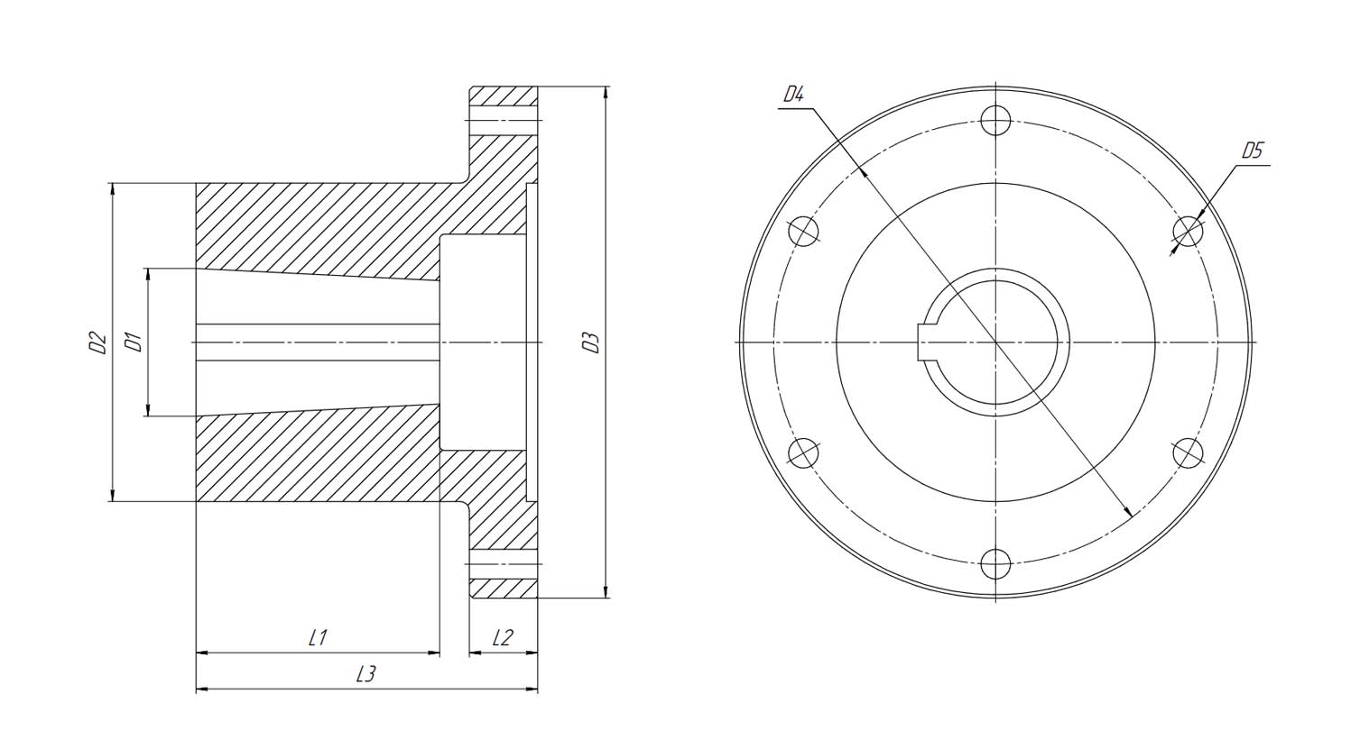
Fig. 4. Drawing of the MZ coupling in version without mating half-coupling.
Table 3. Specifications of MZ couplings without mating half-coupling
Тип
D1min
D1max
D2
D3
D4
D5
L1*
L2*
L3*
nБ
Масса,
кг
МЗ-1
30
50
100
160
140
13
60
20
132
4
8
МЗ-2
30
55
125
185
160
13
107
30
137
4
13
МЗ-3
50
75
140
225
195
17
107
30
150
6
18
МЗ-4
65
90
180
265
230
17
230
107
150
6
39
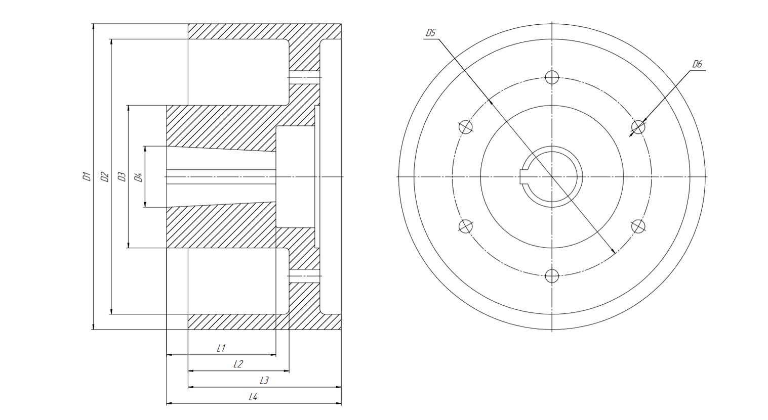
Fig. 5. Drawing of the MZ coupling in version with mating half-coupling.
Table 4. Specifications of MZ couplings with mating half-coupling
Тип
D1
D2
D3
D4min
D4max
D5
D6
L1*
L2*
L3
L4*
nБ
Масса,
кг
МЗ-1
200
170
100
30
50
140
13
60
60
100
110
4
14
МЗ-2
300
270
125
30
55
160
13
107
74
150
165
4
35
МЗ-3
300
270
140
50
75
195
17
107
99
150
171
6
39
МЗ-4
400
360
180
65
90
230
17
230
142
190
200
6
78
* subject to customer agreement
Also, by customer agreement, it is possible to manufacture MZ-1 half-coupling with Ø160 mm brake pulley and MZ-4 with Ø500 mm brake pulley.
The final stage of coupling production is through hardening of the gear rims of hubs and sleeves to a hardness of 42 … 51 HRC.
Our company manufactures hubs of gear couplings with a straight-line tooth profile. Thanks to side clearances and the spherical shape of the outer teeth, shaft misalignments are compensated. This occurs due to tilting of the hubs relative to the sleeves. The coupling design allows compensation of axial and radial displacements of the connected shafts. Shaft end bores are cylindrical or conical.
We produce couplings with an involute tooth profile and a pressure angle α = 20°, with normal accuracy grade, for circumferential speeds at the pitch circle of less than 15 m/s.
The “Gruzopodyom” plant manufactures gear couplings with the following design features:
Tooth flank roughness Ra 2.5, reducing friction, ensuring uniform load distribution, and increasing service life.
Shaft bores are cylindrical or conical; after machining to the required diameter, keyways or splines are cut according to the customer drawing.
The design includes grease fittings to supply lubrication to the gear mesh, and seals protect working surfaces from contamination and leaks.
Couplings can be made with or without brake pulley, and with or without mating half-coupling.
Teeth are heat-treated to increase load-bearing capacity, ensuring durable operation under high loads and frequent start-stop cycles.
It is important to note that during operation, possible deviations in the hub and sleeve construction may cause uneven load distribution among teeth, leading to bending loads on shafts. Additionally, when the shaft axes are misaligned or radially displaced, friction forces arise on tooth flanks, creating bending moments in the misalignment plane. Therefore, we recommend ordering this product from companies with extensive experience and qualified engineering staff.
Since 2008, “Gruzopodyom” has been designing and manufacturing crane equipment. We have the necessary competencies to produce gear couplings. Our production is equipped with modern CNC machines, allowing high-precision manufacturing in a short time. Each order comes with detailed drawings indicating dimensions of all parts, steel grade, and product weight.